176
1

I have a 12v 6.67A power supply with a male co-axial plug (with centre pin) that's 7.4mm OD and 5.08mm ID. The metal tube is 12.5mm long.

The pin is recessed and about 1mm in diameter - which seems impossibly small for 6.67A.

A chassis mount socket that would take it would come in handy. But I don't seem to be able to find one. Am I just using the wrong search terms?

Any pointers much appreciated.

177
1
submitted 1 year ago* (last edited 1 year ago) by Saigonauticon@voltage.vn to c/askelectronics@discuss.tchncs.de

So I wanted to design a children's toy, where the electronics could last 100 years (ignoring mechanical abuse). I figured some people here might be interested.

I settled on a CR2032-powered night light, using an attiny10 microcontroller, where the flash is rated for 100 years unless you're writing to it (which I am not). I did some pretty heavy power optimization. The firmware is hand-optimized assembly.

When you turn it upside-down, a tilt switch toggles an LED @ 3mA via a pretty intense debouncing routine.

A watchdog timer has it auto power off in 30 minutes.

When off, it consumes less than 1 uA. So it has about 25 years of standby time, although the battery is only rated for 10 years (it is replaceable though).

If a child uses it every day, then the battery should last about 4.5 months.

I made custom boards for it -- I kept is simple with few components as possible (resistor is for scale):

I kept assembly simple. A better design would snap right in to the pins of the CR2032 holder, but that's an addition I'll make another day. I also should have added one more ground pad to solder to, but forgot. Still, an OK result I think.

I used some spay-on lacquer to protect the traces a bit after assembly.

178
1
ESP32 with multiple cameras (discuss.tchncs.de)

I want to connect five OV2640 cameras via FPC to an ESP32 on a custom PCB. Is this generally possible and does the ESP32 have enough power for this or do I need an ESP32 for each camera? The frames per second are not so important as the cameras will be used as QR code scanners. Which components allow to run so many cameras with one ESP32?

179
1
Extra Long Pin 2x2 header (discuss.tchncs.de)

I'm looking for a version of this connector (2x2, 2.54mm):

https://www.adafruit.com/product/4855

with extra long pins, like this: https://www.adafruit.com/product/2223

Any sources for this?

180
1

A comprehensive mapping of old subreddits to new communities.

181
1

Since I never understood op-amps from reading or practicing problems I wanted to build a circuit to probe around and use different resistor values to set the amplification.

Currently I am attempting to build an LM358 Non-Inverting Op Amp. I am using my power supply for a +/- 12V rail, and my Arduino Uno for my 5V supply at the V+ input pin. I have chosen two 1k resistors to amplify the signal to 10V at the output and put and led as a indication that the circuit is working.

My questions are as follows:

  1. Is the ground for the voltage rail and input signal the same?
  2. What exactly is wrong with the circuit I built? I want the LED to only turn on when 5V is supplied at the input, right now the LED can turn on if I connect the ground to the voltage rail supply even without an input voltage.
  3. I've seen the post on Adafruit with the feedback resistors connected to the same ground as the rail supply, but the circuit diagram does not show where the input voltage ground is? Link: https://blog.adafruit.com/2012/06/13/ask-an-educator-making-a-non-inverting-op-amp-circuit-on-a-breadboard/
182
2
submitted 1 year ago* (last edited 1 year ago) by Double_A@discuss.tchncs.de to c/askelectronics@discuss.tchncs.de

Is there a reason why the banner and logo of this community are just the reddit logo?

To be honest that doesn't seem very appropriate, nor is it very pretty.

183
1

What I've done is take a large 2n3055 BJT NPN power transistor, and decap it (it is a large metal-can type). Then I carefully removed any coating from the exposed silicon (it typically has a dab of silicone potting compound on it).

Then, I had a weak alpha source at ~5MeV lying around the lab from previous work. This was inserted into the can with the beam facing downward towards the exposed silicon, and the can reattached and made lightproof.

Then I threw together the circuit shown here using the modified transistor (the base is left floating). What I expected to happen was that at TP1 (relative to GND), with my scope AC-coupled, I should see small voltage spikes followed by a decay. This is caused by alpha particles impacting the silicon and knocking loose enough electrons to permit some current flow.

However, I just see... more or less nothing, maybe some electrical noise from fluorescent lamps in the room next door. Certainly not the spike+decay curve I've seen with other detectors.

Did I make a wrong assumption somewhere? It's been a while since I worked with discrete transistors much, and I feel like I am missing something silly.

Or is this more or less right, and I should maybe question whether my alpha source is still good? Or whether the signal strength is in a voltage domain I can even clearly see without amplification? Or maybe I should suspect that a thin passivating glass layer is added to big BJTs these days, enough to block the alpha?

The source is past expiry, but not by that much. I'm mostly interested in characterizing and documenting the detector as an academic exercise.

184
2

I've wondered this occasionally over the years, but never got it working.

I tried just putting a dried piece of chicken bone pressed between two plates (mild compressive stress perpendicular to the bone), and using an inverter just like I would use a crystal. It did not work. Maybe I need a really thin segment?

I have no practical application in mind. I might make a CPU from it for Halloween I guess?

I'm not sure if I would classify it as electronics or necromancy, but I thought it was an interesting question to ask here :)

185
1
LM337 problem (discuss.tchncs.de)

Hello, I have a strange problem with the LM337 regulator. I have built a classic LM317/337 power supply - and it works, giving proper voltage, etc. however when I start it under load (approx. 300mA per regulator) using a switch, the LM337 goes into some sort of protection (audible buzz), but when I start the circuit under load using on/off switch on my laboratory power supply (I think the input voltage is rising then slower) the LM337 works as normal. I heard that when the LM317 is starting as first, then such effect may occur (but I don't know anything about this). What would be your first suggestion in solving this problem?

186
1
Did I damage my crystal? (discuss.tchncs.de)

I bought a random cheap crystal oscillator off AliX. It was advertised as a "constant temperature crystal reference".

I also didn't know what voltage it took. I found a photo of a similar one which apparently needed 12 V. However, smoke started coming out when I tried 12 V.

It seems to oscillate OK on 5 V though. However, it seems to be fluctuating in frequency, and I don't know if this is normal, or whether I have damaged it.

187
1

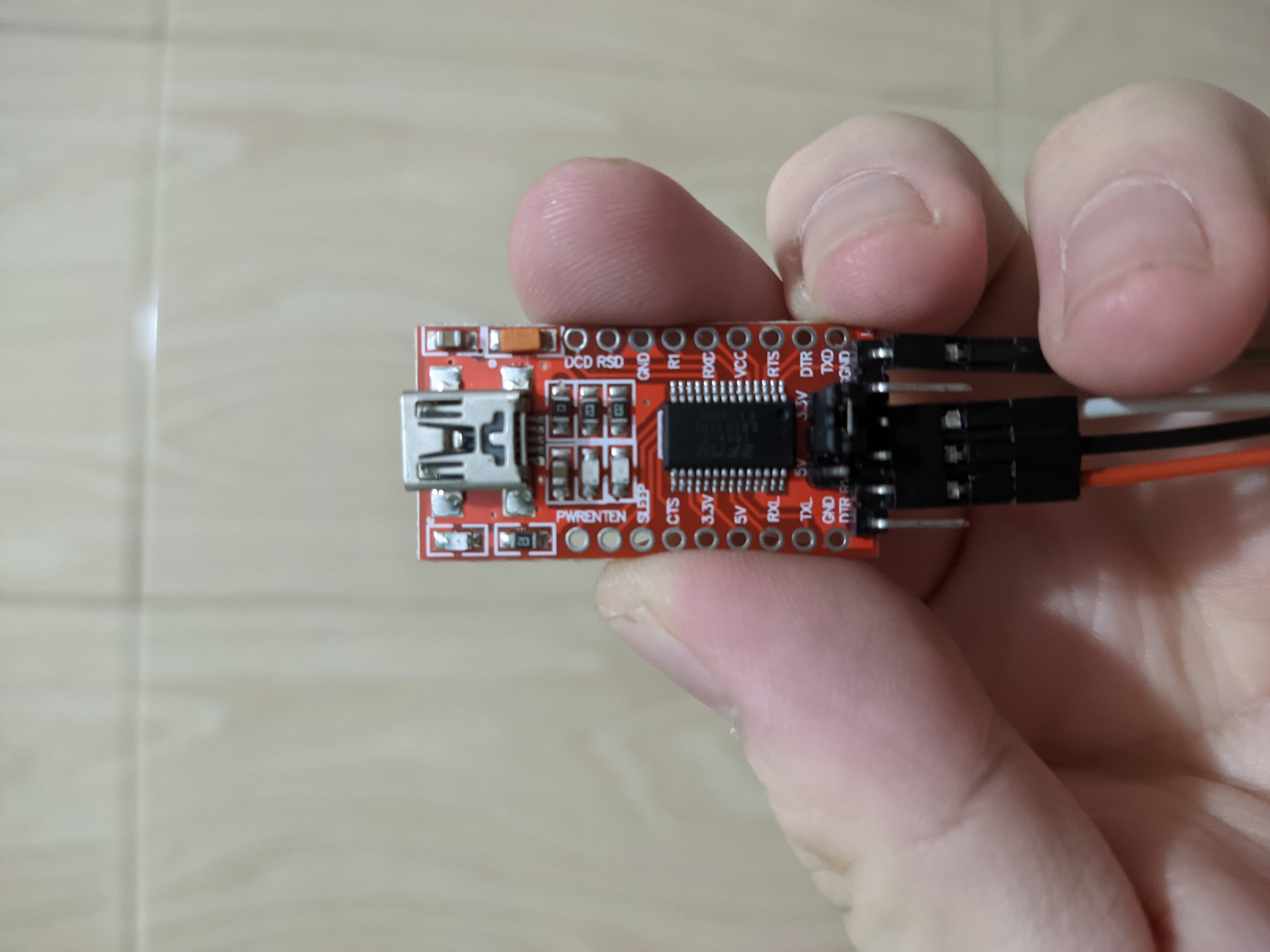
Bought it a long time ago and can't remember. There's a jumper cable and I remembered using it to flash something. I only dabble with Atmega32U4, Atmega328p and stm32 blue pill, so it's probably either of them.

Or maybe my brain short circuited and it's a totally different hardware.

I actually needed an AVR flasher to fix a pro micro with corrupted bootloader that cannot enter dfu mode. So I want to make sure I don't have it before buying a new one.

Thank you!

188
1

I'm getting a little bit frustrated with my AliExpress 2.54mm dupont ribbon cables. The female housings get loose after just a few cycles, and the connections start falling apart easily.

I've gotten some Amphenol Mini-PV 47649-000LF, which are amazing and are close-enough to being compatible with a standard dupont housing. But it's a hassle to crimp the wires myself, especially when I just need another female-female 6in wire.

Lots of stuff on the internet, but it's impossible to tell when it's actually good and when they just repackaged AliExpress. Anyone have a vendor they've had good experiences with? Ideally multi-color, but I'm flexible on that.

189
2

Hi all

I'm working on a DIY 18650 lithium ion home battery, built out of old laptop/ebike cells that have been tested for performance (capacity, internal resistance and temperature during cycle) and found to be good enough for use.

There are several safety precautions in my setup. Each cell has a 1A current fuse and a 60C thermal fuse attached to it(in series). Should a cell overheat or develop an internal short, the cell gets deactivated easily without fancy electronics. (protip, don't hotglue thermal fuses!) The BMS is a DALY BMS rated for 60A, although I'll probably never use it above 30. Additionally, an Arduino monitors the individual cell voltages as well as overall temperature (secondary BMS that can communicate over serial to a proper webserver.). This Arduino also watches a smoke detector and controls a solenoid killswitch should anything fishy happen, like overvoltage/temperature or the smoke sensor triggering.

This may or may not be a bit overengineered but I want to leave this system running pretty much autonomously with several layers of safety. A Chinese BMS on its own is not good enough and a professional one is outside my budget. Also the learning process is worth the effort.

Should, god forbid, a cell actually catch fire despite all safety measures I want to have the battery in a fire safe container as well. An iron cabinet like the IKEA Lixhult won't melt in case of battery fire but it will vent hot fumes that could set surrounding objects on fire. What would be a good way to engineer that? A metal cabinet with a metal chimney attached to it? So that the hot fumes get directed away from flammable objects? Perhaps something built out of stone where sand bags may be placed above the battery. Fire would cause the sand to drop on the batteries and smother it.

There isn't any way to crosspost on Lemmy right?

190
2
191
1

Hi everyone, I've just resurrected a broken Weller TCP1 and need a 24v ac supply for it.

I have a 23.5-0-23.5v toroid that I was just going to use half the winding - but it's overkill (8A rating) and going to be very big and heavy.

I've also got a pair of identical transformers with 8-0-8 and a 16-0-16 secondary windings.

I'm thinking of paralleling a 16v winding on each transformer, doing the same with an 8v winding and putting the two in series to give the 24v. However, that leaves two 16v windings and two 8v windings left unused.

Is there any advantage in paralleling those windings also? Any disadvantage? Or just leave them unconnected...Which is what I was about to do..

Sadly I cannot split either winding into two independent ones.

192
3

I'm interested in learning how to make a proper PCB rather than perf board with wires all over the place.

193
0
submitted 1 year ago* (last edited 1 year ago) by nirurin@discuss.tchncs.de to c/askelectronics@discuss.tchncs.de

Hi, I'm new here (never used this entire platform before, but as the askElectronics reddit is down I thought i'd follow the trail to lemmy and see what's what). Hopefully this works!

Ok so I have the following -

A variable boost converter This - set to 12v output.

Two sets of 2x 18650 batteries

A 12v LED strip.

The two circuits I'm sanity checking -

  1. Two 18650s in series, outputting about 8v, going to the boost (which ups it to 12v) and lighting up the 12v LEDS.

  2. Two 18650s in parallel, outputting about 4v, going to the same boost (which still ups it to 12v, so that's working fine and seems to be within its working range), lighting up the 12v LEDs.

Question I wanted to check - Far as I am aware, both of these circuits should be fine and do the job. And I'm aware of how series vs parallel usually works (eg. double the voltage, vs double the capacity). However I've never used them with a voltage booster that sets things to a fixed output voltage.

I am assuming that the way the voltage booster works, means it will 'drain' the parallel circuit twice as fast as the series circuit. And so both will end up running the LEDs for the same amount of time. This sounds right in my head but wanted to confirm before I soldered all my connections.

Also wondered if, in this scenario, the general recommendation is to go with the parallel or the series circuit. I wonder if the series might have less losses through the boost circuit through heating etc, but I was just guessing.

Thanks! Long first lemmy post haha. > Unfortunately after posting this I discovered the TP4056 board won’t charge 18650s in series, only in parallel!

Edit: While it seems that running the cells in series would be more efficient, I have the issue that I recharge them using a TP4056 board, and they are only compatible with charging cells in parallel and not in series!

194
1
195
0
submitted 1 year ago* (last edited 1 year ago) by shoeforthepot@discuss.tchncs.de to c/askelectronics@discuss.tchncs.de

I'm planning to add a momentary switch to a single loop DC circuit. Will this cause any amount of resistance in the circuit? I'm a complete noobie when it comes to electronics, any resource links or clarification is appreciated. I know the type of material/width of wire and a pot will cause resistance but will any component put in line with the circuit cause resistance, and if so how do I go about measuring the resistance for each component within the circuit?

196
0
MOSFET as Radiation Detector (discuss.tchncs.de)

Hello, we are making a thesis where we use MOSFETs as an alternative radiation detector. So to explain it, it works when the mosfet is irradiated with an external radiation source; its voltage threshold increases, which will be used to determine the radiation dose. I'm currently asking for help on how we measure the voltage threshold. BTW, we are using an n-channel MOSFET (model: IRFP250NPbF). Also in the datasheet provided by the manufacturer, it says here VGS(th)/Gate Threshold Voltage Min: 2.0 ––– Max: 4.0 V. There is a condition here with VDS = VGS, ID = 250 A. Does this mean that to measure the VGS, we need to first satisfy the conditions? To measure the voltage threshold, what node will we use to measure the VGS (th)? Is it at the drain to the source terminal or still at the gate to the source terminal? Feel free to share your thoughts, if you have any. I would also like to add that we have already tried to supply a voltage at the gate with respect to the source terminal. We use a 4 V supply voltage, and when we tried to measure the VDS (drain to source voltage), there was a voltage drop, so we've got a 3.5 V. Also, we are using an Arduino to measure its voltage and a multimeter for checking.

197
0

I'm working on adding extra access control to elevator calling buttons and i would like to identify the connector type of the wires connecting elevator buttons to the elevator panel

I have tried Micro JST 1.25MM 3-Pin Male & Female Connector Plug, it has the same Pitch Mating size of 1.25mm but unfortunately the connector itself is smaller than the original one.

198
1
Welcome to AskElectronics (discuss.tchncs.de)
submitted 1 year ago* (last edited 1 year ago) by DavideAndrea@discuss.tchncs.de to c/askelectronics@discuss.tchncs.de

This Lemmy community is an alternative to the Reddit /r/AskElectronics

Ask Electronics

3173 readers
1 users here now

For questions about component-level electronic circuits, tools and equipment.

Rules

1: Be nice.

2: Be on-topic (eg: Electronic, not electrical).

3: No commercial stuff, buying, selling or valuations.

4: Be safe.


founded 1 year ago
MODERATORS