8
you are viewing a single comment's thread
view the rest of the comments
view the rest of the comments
this post was submitted on 18 Apr 2024
8 points (100.0% liked)
Amateur Radio
660 readers
5 users here now
General amateur radio (ham radio) chat, questions, and news
founded 1 year ago
MODERATORS


Wait, what do the PCB mods do?
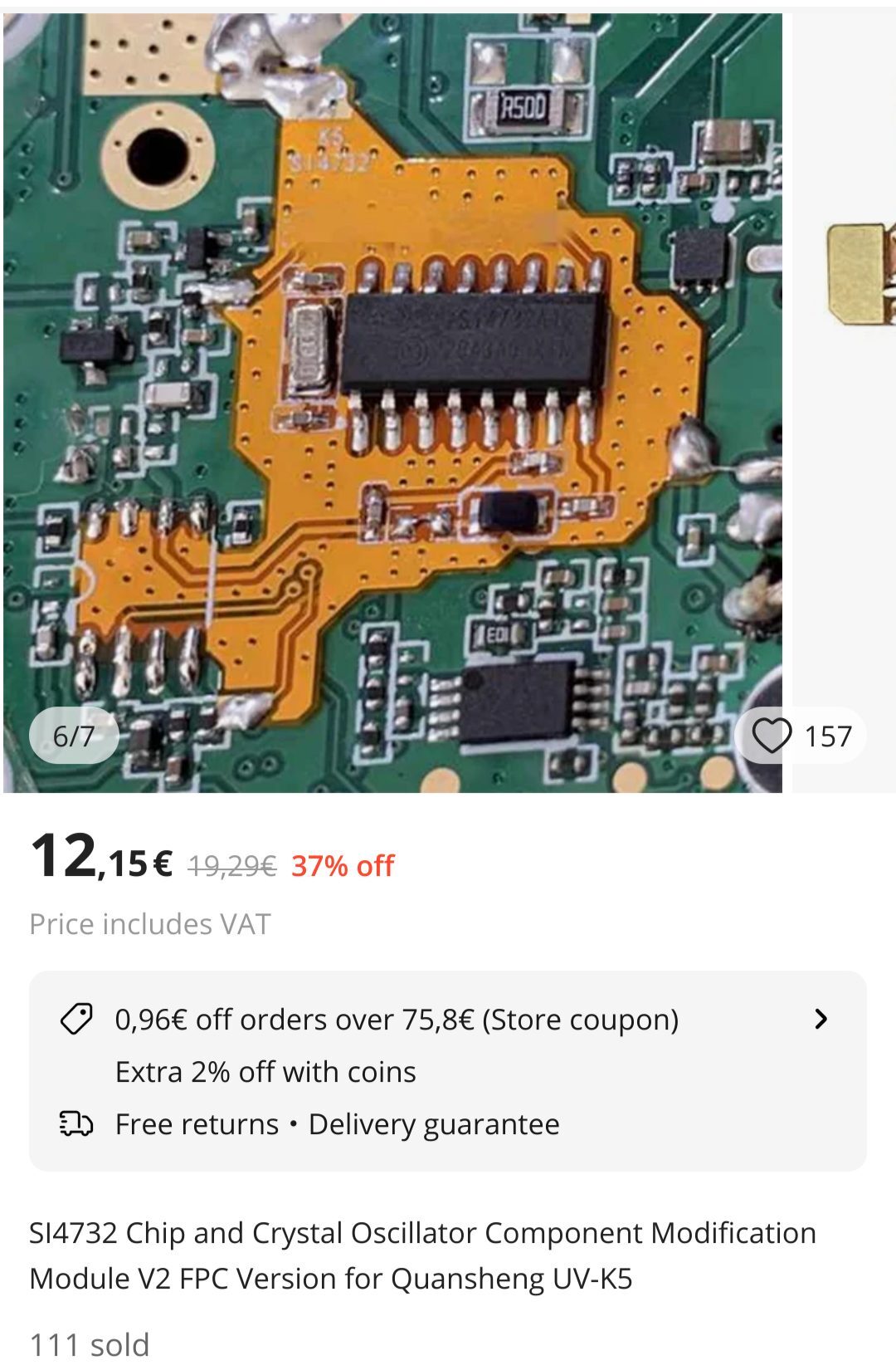
AFAI understand their basic functionality is to extend the frequency range for those UV-K5 devices down to 18 MHz when used with a hacked firmware. At least for RX, everybody warns about not to use a modified device for sending out of band (2m/70cm).
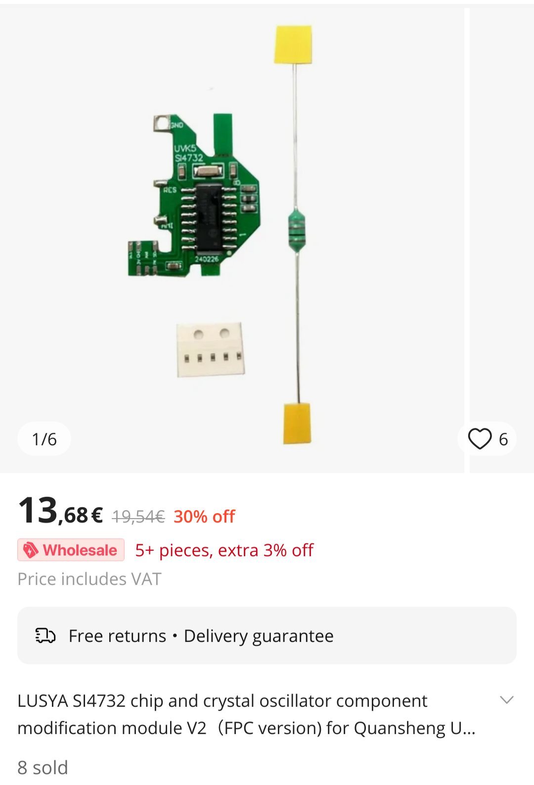
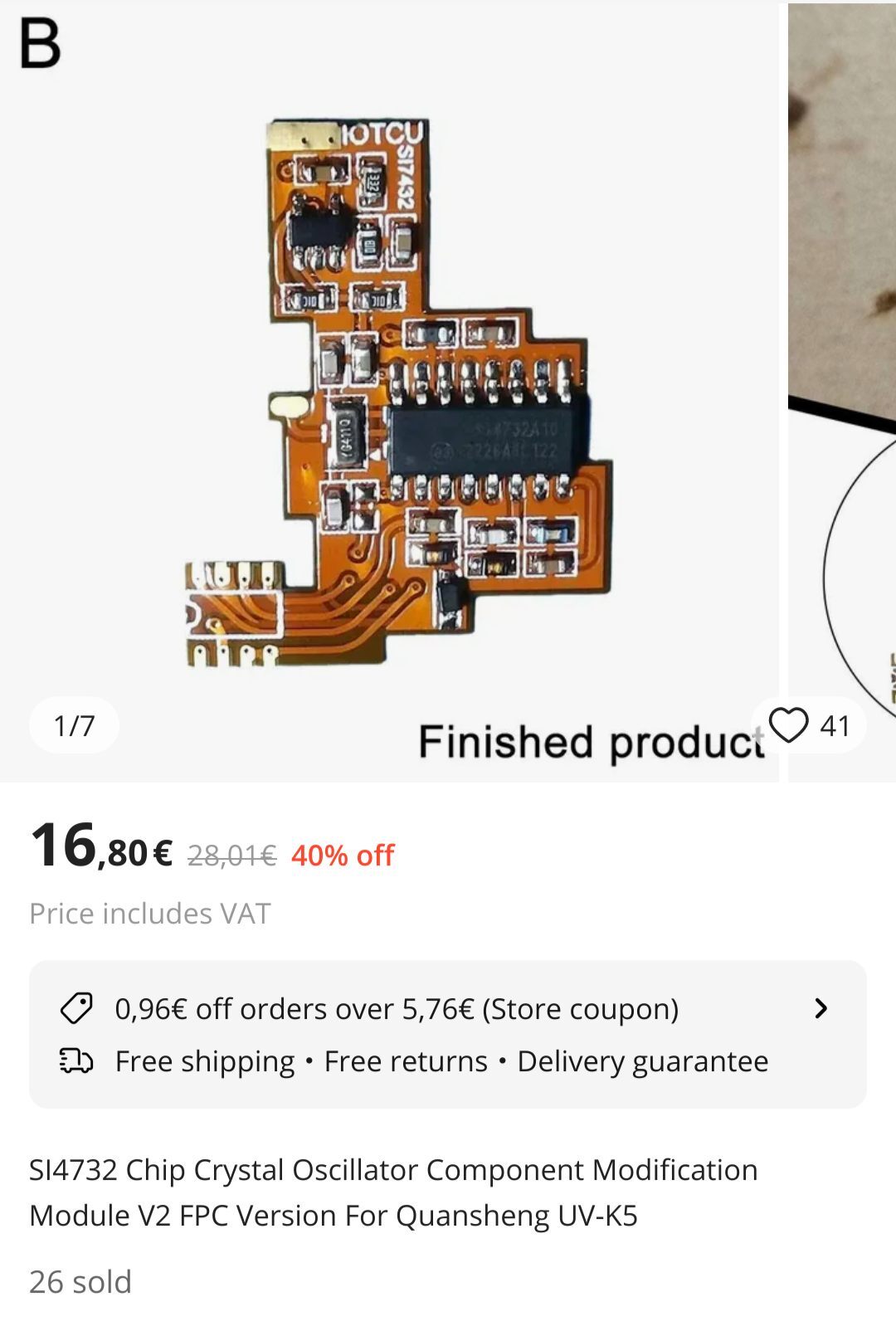
But the green PCB includes a resistor (for replacing the "choke"?) and microscopic SMD capacitors to replace on the radios main board to fix problems (idk which ones) with the radio. The orange boards include neither a separate resistor nor a capacitor, but the big orange board includes a second circuit which seems to be an amplifier to improve SSB volume. This is my interpretation of forum posts & product desctriptions I don't understand completely - thus my original post, hoping to find somebody who's savvy on this topic.