Really, Penfold.
WaterWaiver
joined 2 years ago
Every news website is covering it. I think I've spotted most of 10 articles around the place.
The law of well-marketed unreleased goods dictates that this vehicle is not going to meet any of the promises mentioned in the articles. I hope to be proven wrong, but just like video games: don't pre-order, wait for it to come out and be reviewed.
Thankyou border force for keeping this nuclear threat away from our shores. I hate to think what a growing market of periodic table and sample collectors could do to our great country.
I suspect that you need to think of the 3 B->E voltages as inputs (OR'd with each other) and the C->lowestvoltageE path as the output. All of them are operating in linear mode too, I think one of them is a low-gain follower whilst others have a lot more gain. Maybe.
~~Nope, bottom right and top middle >:D~~
Oh my god I've forgotten what a base is. This transistor is doing my head in.
I don't want my children influenced by this. "Dad why does your transistor only have 3 legs?". And I had only just rid the house of dual-gate mosfets too!
I only know what wikipedia tells me about these things, I've never played with one. I also have no clue yet what it does in this circuit.
3 emitters and 2 collectors.
The headline and text of this article were amended on 24 March 2025 after the Guardian was notified of a significant calculation error in the Queensland Conservation Council research. An earlier version said the dams that supply the proposed Callide and Tarong nuclear plants “could not access enough water” to cool them in the event of a meltdown; our article has been amended in line with the organisation’s revised analysis.
Source: bottom of amended article.
That's a CH340G, it has an in-built 3.3V regulator. But there is no external regulator on the board.
Maybe the chip is running off its internal 3.3V, but the board designers put a tie-up resistor on one of its pins to 5V, which results in the weird 3.9V. Dunno. Try attaching a 1K resistor between that pin a GND, see if that makes the problem disappear.
The 5.3V is from your computer, that's not the fault of the USB UART.
3.2V is perfectly acceptable for a 3.3V rail.
The 3.9V is a bit weird. Can you post a photo of your USB UART board? Maybe the main chip has an inbuilt 3.3V regulator separate to the external one.
Stand back, I'm carrying a budgie smuggler.
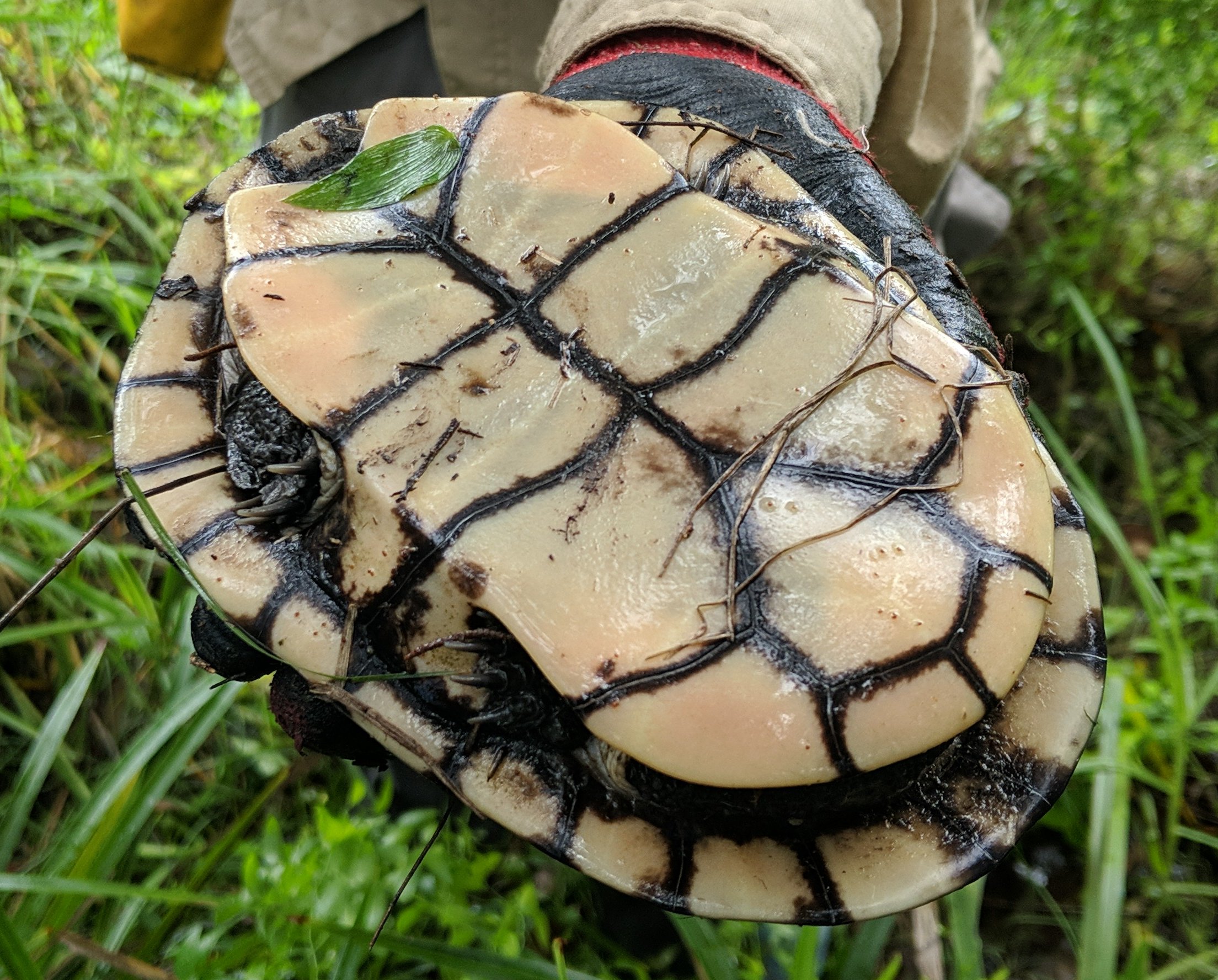
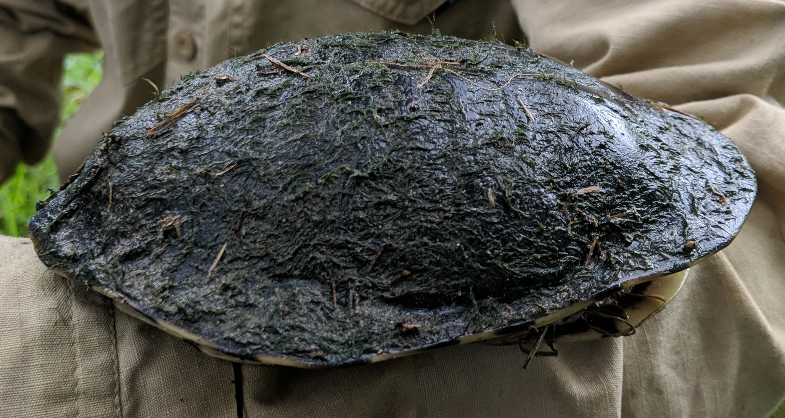
Encountered this fellow during bushcare today. He was sitting right on top of the bridal veil roots we were pulling, looking suspiciously like a rock.
We probably shouldn't have handled him (I hope turtles don't get dizzy from being turned upside down). We put him back down and hid him under some other groundcover as a local Kookaburra was loitering.


Imagine you're in the blue car, wanting to turn left:
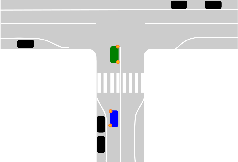
Green is turning right. There is only one lane.
Two options I see:
(1) Stay behind the green car, to the left (and behind the crossing) until they leave.
(2) Pull up to the left of the green car (as if there were two lanes).
I assume (1) is correct given there is technically only one lane, but I can't find any materials on the NSW site or driving handbook about it and (2) is something I see other people do.
(I have my license test next week)
EDIT: Solved, option (2) is the right one. see https://www.nsw.gov.au/driving-boating-and-transport/roads-safety-and-rules/sharing-road-overtaking-and-merging/overtaking-safely
The only time you can overtake on the left is when the vehicle you’re overtaking is:
- waiting to turn right or make a U-turn from the centre of the road
8
I've discovered that my phone camera is doing some magic processing. Do you know what it's called?
(aussie.zone)
I accidentally held down the photoshoot button on my phone and ended up with a sequence of photos of the same scene taken over about 1 second. Interestingly the series of photos contains two very different styles of image:

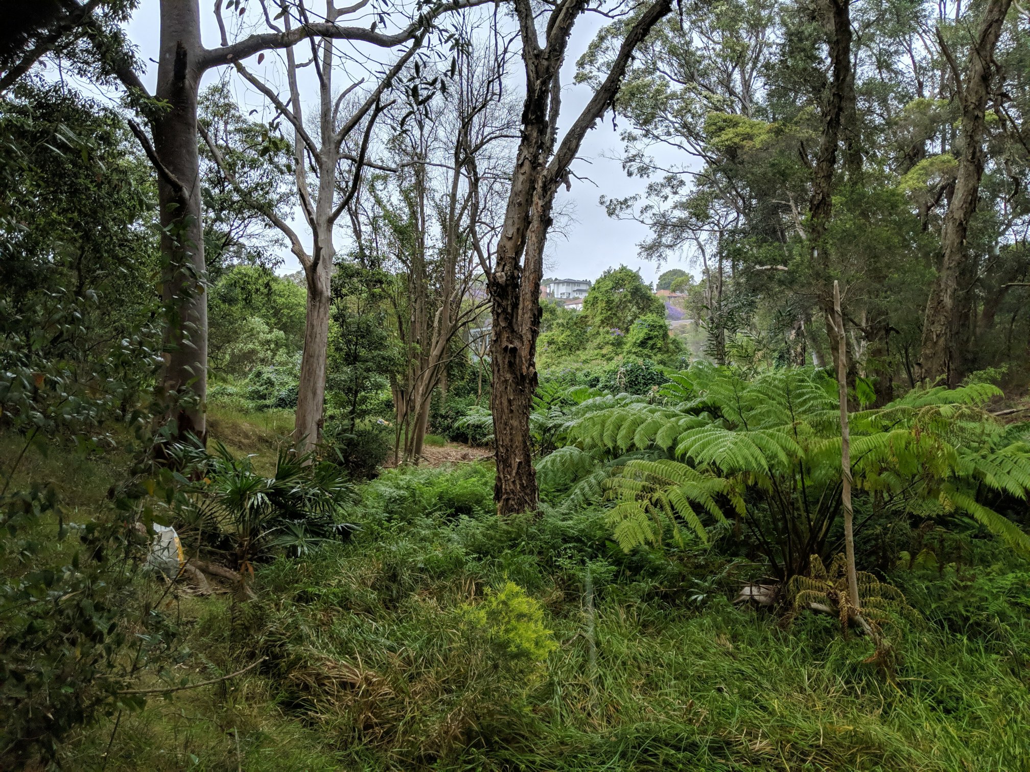
The first photo looks how I'd expect. Sky is overblown from the clouds and foreground of the forest is dark.
The second photo has somehow magically made the sky darker and the foreground brighter.
At a guess I think a software algorithm is trying to separate the foreground and background, then individual levels adjustments are being applied to each region. Checkout these two close-up crops:
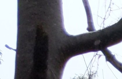

The first photo shows what I'd normally expect from a camera (bright light bleeding into the trunk), the second shows a white halo around the trunk on the sky (probably artificial/software blending from foreground to background). I think I can also see see some evidence of artificial sharpening on the trunk texture; or perhaps the photo was just better in focus (some of the photos were a bit blurrier than others).
I'm using a Pixel 3 with OpenCamera.
Does anybody know what this feature is called and more info about it? I'm particular interested in how binary it is -- it's either activated or not -- some some heuristic must be involved.
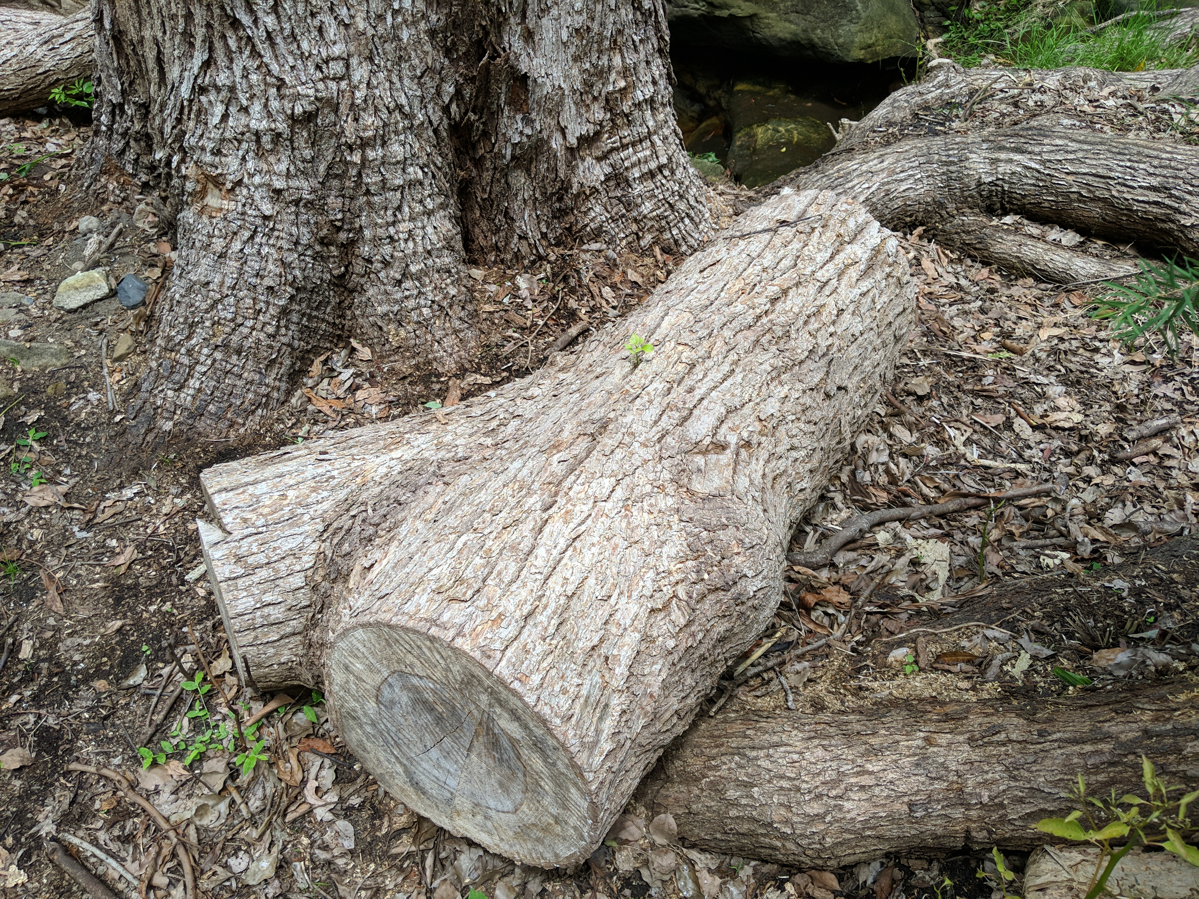
Spotted at my local bushcare group last week. This trunk section has been sitting on the ground for months. The main tree (background) was hacked apart, drilled and poisoned by NSW Forestry, but it's also happily sprouting everywhere again.
Camphor laurels are beautiful, toxic trees that you will see everywhere but sadly they're also weeds. The ground near them tends to be barren, they intentionally poison the soil (allelopathy) to avoid competition. I've been told that they were used to make shipping boxes because their wood resisted insects
That (chinook-style solution) only works if both rotors are the same size and speed.
Perhaps Sikorsky's tethers to the ground worked around the problem for that photo anyway. Not sure.